RAL Space were involved in the development of SMART2, an ESA Mission which then became the ESA LISA Pathfinder mission, launched in 2015.
The mission demonstrated the operation of a drag-free spacecraft at a level better than the goal of 3.10-14ms-2Hz-0.5 at 10-2 to 10-3 Hz. This is suitable for the drag-free performance that will be required for LISA. The results are reported in “Sub-femto-g Free Fall for Space-based Gravitational Wave Observatories: LISA Pathfinder Results" Physical Rev. Letters, 10th June 2016.
RAL Space were involved in the following crucial technology developments:
- Design and manufacture of the engineering model optical bench for the laser-interferometer that measures the relative motion of the proof masses in two inertial sensors. This was used in ground-tests in 2003 to demonstrate the technology-readiness of the LISA-pathfinder payload. This included demonstration of pico-metre level stability in the measurements. Here ESA's prime contractor was Astrium-D with other subcontractors: Universities of Glasgow and Hannover, and TNO-TPD. For the subsequent flight model University of Glasgow became the supplier of this optical bench.
- For the Inertial Sensor which measures the motion of the satellite, RAL developed, with AEAT and SULA, a caging mechanism to enable the proof mass to withstand launch vibrations without damage which would upset the very precise electrostatic sensing. Involved in other aspects of this sensor are Univ. Trento, ICSTM, and Univ.Birm, co-ordinated by ESA's prime contractor Carlo Gavassi Systems in Milan.
- A neutraliser (electron emitter) for the Field Effect Electric Propulsion Thrusters; funded by ESA.
- A collaboration led by Prof J Stark at QMW to develop electro-thrusters based on an electro-spray technique; funded by EPSRC and STFC.

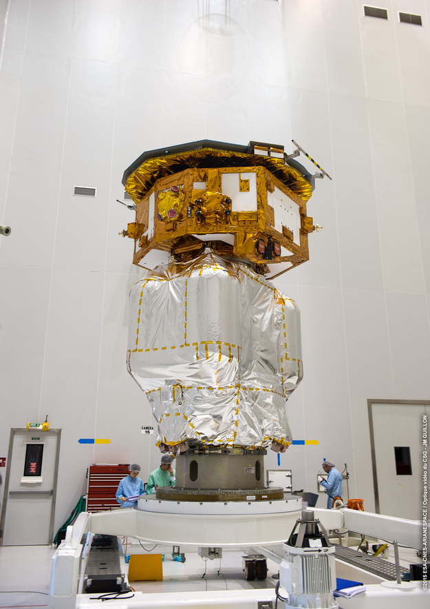
Image: The LISA Pathfinder spacecraft composite being prepared for fuelling.
Credits: ESA-CNES-Arianespace / Optique Vidéo du CSG - J.M. Guillon
RAL Space Involvement
Inertial sensor development, optical bench, and micro-thrusters (Engineering models, 2003).
Subject
Fundamental Physics
Main Objectives
Developing technology for LISA mission
Launch Date
Dec 2015
Partners
ESA, ESTEC, European Space Operations Centre, NASA, AEI, APC, IEEC and more.
Further project information
Imaging
The Imaging Systems Division was part of the team that designed, manufactured, built and tested the engineering model of the optical bench, which is the central part of the interferometer in the LISA Pathfinder spacecraft. This is a much smaller interferometer than LISA; it will measure the position of two test masses in the same spacecraft, separated by about 300mm, but it will demonstrate the drag-free technology needed for the detection of gravitational waves in the LISA mission.
The optical bench, which comprises four separate heterodyne Mach-Zehnder interferometers, is made from twenty fused silica mirrors and beam splitters which are bonded to a Zerodur base plate through a method called silicate bonding . The LISA Pathfinder interferometer requires stability levels close to those of LISA itself, and to achieve this demanding requirement materials and construction techniques must be carefully chosen for high levels of mechanical and thermal stability.
One of the challenges of the construction technique was the short time – around 30 seconds – available to position the parts before the silicate bond cured. Added to this, some parts had to be positioned to better than 30 seconds of arc for the interferometer to work with high enough contrast. Within the Imaging Systems Division handling techniques to align the parts during bonding without placing stress on the bond-line during curing were developed. Using these techniques all the optical components were successfully bonded in place to produce a working optical system.
The finished interferometer was tested and performed as expected, meeting its measurement and stability goals.
For more information please contact: RAL Space Enquiries
